Elster PR6 and PR7 electronic pulse meters
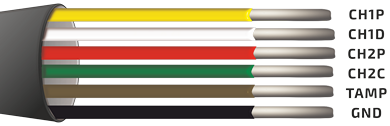
Pin designation of Honeywell Elster PR6 and PR7 pulse meters:
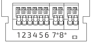
OrionMeter pin layout
-
OrionMeter LA-IP— three discrete/pulse inputs (IN1 - 1,2; IN2 - 3,4; IN3 - 5,6) -
OrionMeter LA-IP [4O]— four discrete/pulse inputs (IN1 - 1,2; IN2 - 3,4; IN3 - 5,6; IN4 - 7*,8*)
The connection of the output contacts of the pulse meters should be performed according to the table below:
| Contact | Color | Description | Status | Connection to inputs OrionMeter |
|---|---|---|---|---|
| CH1P | Yellow | Forward and reverse output pulses (must always be connected) | Active, "LOW" | To any available contacts 2/4/6/8* |
| CH1D | White | Direction flag | "LOW"; Forward flow — "HIGH" | To any available contacts 2/4/6/8* |
| CH2P | Red | Adjusted volume pulse — forward flow minus backflow. During a backward flow no pulses are send to the output. After renewed forward first the pulse numbers which are stored in the memory will be deleted. This pulse numbers are generated from the previous backward flow. After deleting the memory forward pulses will be send to the output only. | Active, "LOW" | To any available contacts 2/4/6/8* |
| CH2C | Green | If currently a backflow compensation progress - Backflow Compensations Flag | "LOW" | To any available contacts 2/4/6/8* |
| TAMP | Brown | Alarm flag, signalizes the removal of the pulse meter from the register or low charge of battery | Active, "HIGH" | To any available contacts 2/4/6/8* |
| GND | Black | Ground | To any GND contacts 1/3/5/7* |
info
The OrionMeter LA-IP [4O] device contacts marked with *
Depending on the connected inputs, you should correctly configure Digital inputs