Connection
OrionMeter LA-IP-MBUS device is designed as a compact device in a polycarbonate enclosure with a cap and a cable gland for sealing.
Inside the case, there is a printed circuit board with a terminal block for connecting external devices.
A sealed cable gland M10 is installed on the cover of the case, designed for connecting a cable with an external diameter of 2 to 8 mm.
Inside the cable gland, there is a seal that ensures the declared degree of protection for the housing:
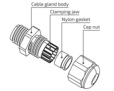
The package includes three sealing rings for different diameters.
Sealing Rings Included
| Sealing Ring | Supported Cables | Dimensions |
|---|---|---|
| M10 (3–8 mm) | One cable with a diameter of 3–8 mm |  |
| M10 (2–5 mm) | One cable with a diameter of 2–5 mm |  |
| M10 (2×2.8 mm) | Two cables with a diameter of 2.8 mm each |  |
The cable should have a round cross-section. Choosing the wrong sealing ring will compromise the device's sealing.
Opening the Housing
To connect the cable to the device, follow these steps:
- Unfasten the cable gland ring and remove the DIN rail retainer by pulling it down of the housing cover.
- Hold the device in one hand so that the logo is on top.
- With the other hand, grip the cable gland, Gently bend the cable gland downward while slightly moving it away from the housing until you hear a click - the bottom cover will open.
- Once opened, you will have access to the terminal block and connectors for connecting external devices.
Do not apply excessive force, twisting, or rotating movements — this may damage the latch or printed circuit board. If the cover does not open, check if the cable in the cable gland is obstructing it.
Connecting Metering Devices
The radio modem's circuit board provides 1 or 3 pairs of clamping contacts.
Metering devices are connected to the IN1 input.
Connection Diagram
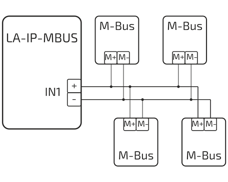
The maximum number of connected metering devices (MD) is 4.